
The waterline endings of a radio yacht can be determined with a water surface bar. A typical water surface bar is shown below.
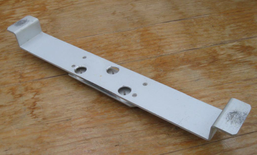
The water surface bar has three length adjustable pins with lock nuts threaded into a plate mounted below the main bar. The pins are metal thread screws the ends of which have been machined to a sharp point. They are aligned with three holes in the top bar as shown in the illustration. The points of the pins are adjusted to be exactly level with the top surface of the bar and the lock nuts are tightened.
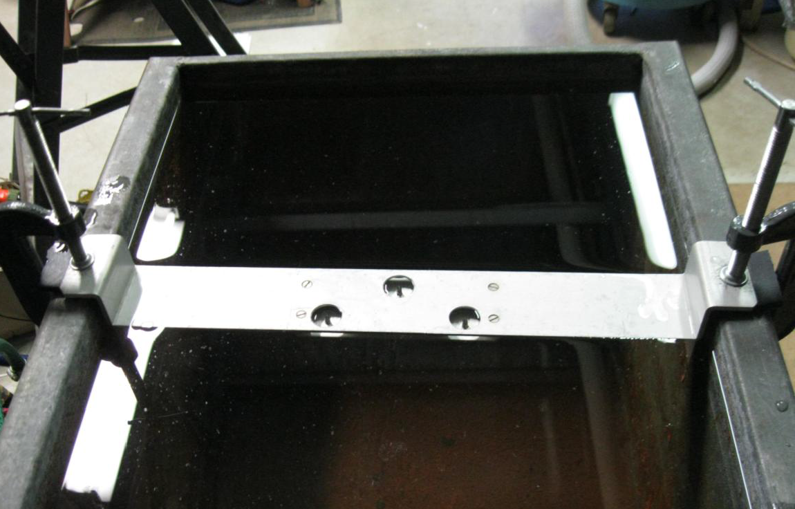
The bar is attached to the top of the tank with some means for a small amount of adjustment. The water level and the bar are adjusted until all three pin points are exactly at the water level. The outside pins ensure the bar is horizontal side to side and the centre pin ensures the bar is horizontal fore and aft. This ensures that the top surface of the bar is at the water surface and eliminates the problems otherwise encountered with water meniscus.
One simple adjustment method is to clamp the bar to each side of the top of the tank with a piece of stiff rubber between the bar and the tank. The bar can be adjusted by compressing the rubber with the clamps. This is illustrated below.
The following procedure is used to locate the waterline endings.
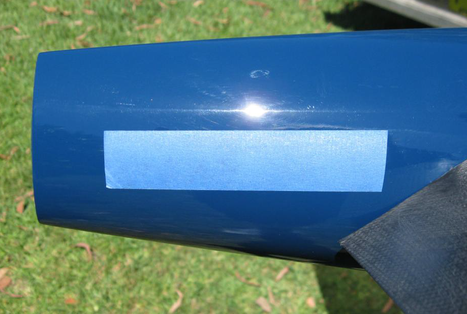
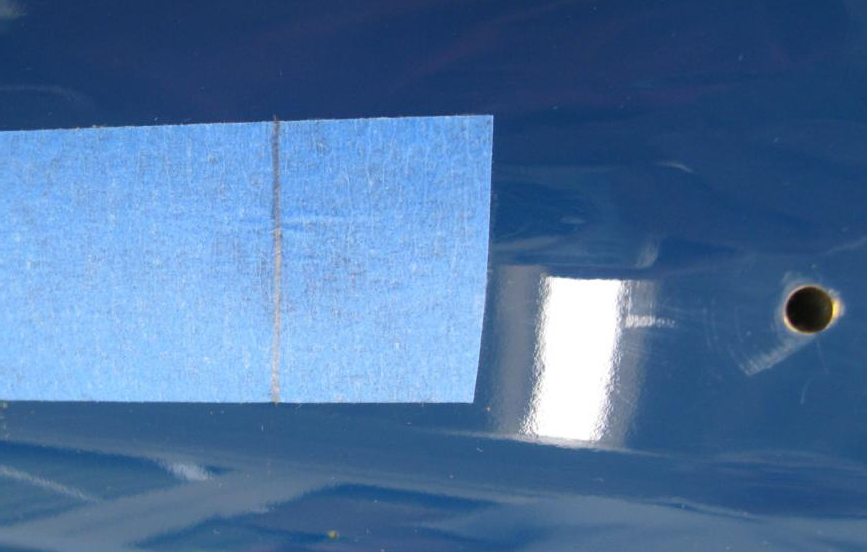
1. A strip of thin masking tape is fixed to the centerline of the undersurface of the hull covering the estimated position of the waterline ending.
2. Place the boat in the tank, wait for any water disturbance to dissipate and adjust the water level to the correct position by observing the pin points.
3. By gently moving the boat fore and aft and gently pressing down on the boat at a position approximately above the bar it is quite easy to determine the position where the boat transitions from moving down to not moving down. This is the position of the waterline ending.
4. At this position press down more heavily to hold the boat in position and mark a line on the masking tape with a sharp pencil along the edge of the bar. The pencil is deployed under water. The masking tape provides a little extra friction to hold the boat in position.
5. Hold a sharp blade against the tape at the pencil line and peel away the tape on the outside.
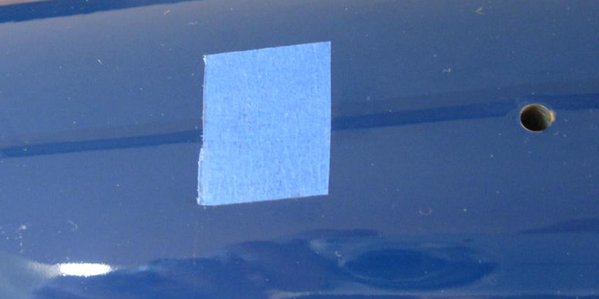
6. Place a strip of tape at least 25mm long against the position of the cut. Automotive striping tape works well. A painted line can also be used.
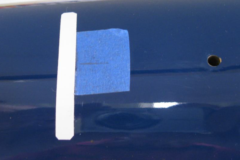
7. Remove the rest of the masking tape. Repeat the sequence for the other end of the boat. Use trammels to measure the waterline length between the inside edges of the waterline marks.
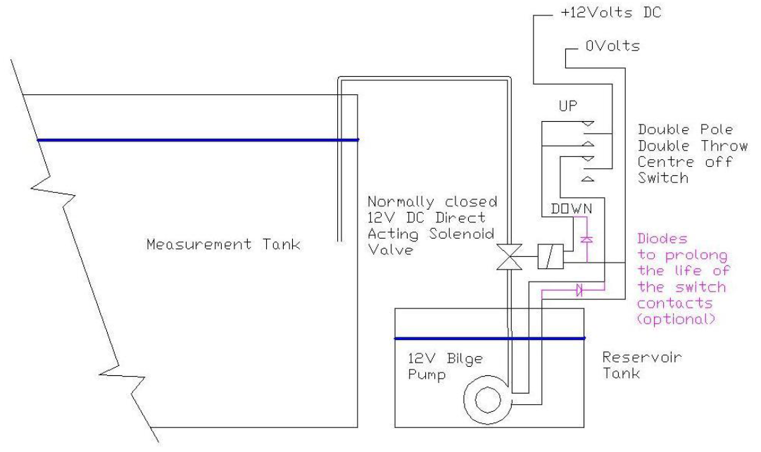
A convenient water level system can be constructed with a 12 volt bilge pump, a direct acting 12 volt dc solenoid valve, a double pole, double throw, centre off switch and a 12 volt battery or a 12 volt dc power supply.